Feature Tour
A visual walk through what Phidler can do. If you'd rather build something hands-on, jump to the MZI Tutorial. For the full reference, see the User Guide.
Open or start a project
Launching Phidler opens a recent-projects list. Pick up where you left off, browse for a file, or start fresh (which opens Project Settings to choose a material platform).

The workspace
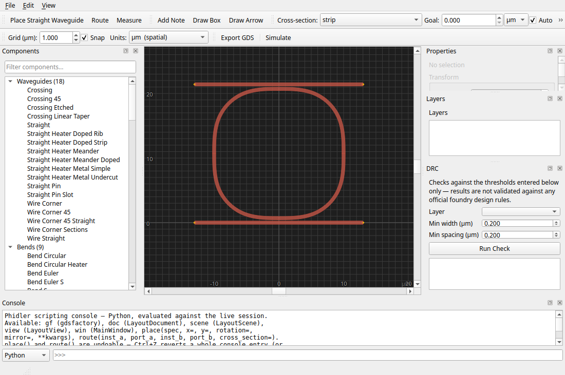
One window holds the whole flow. A searchable component palette sits on the left, the canvas in the middle, and docked Properties, Layers, DRC, and Console panels on the right and bottom. Toolbars across the top carry the place / route / measure tools and the grid, snap, units, export, and simulate controls.
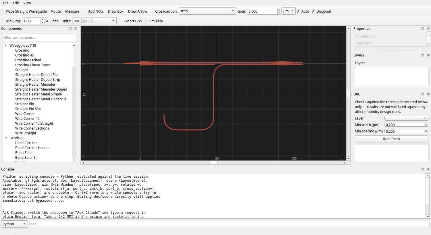
Place components
Every gdsfactory PDK (process design kit) component is in the palette, grouped by kind. Type in the filter box to narrow hundreds of factories down to what you want, and hover any entry for a live rendered preview before you place it.


The catalog is the whole gdsfactory generic PDK, grouped by kind: waveguides, bends, couplers, splitters, rings, gratings, edge couplers, and more.

Selecting a placed component opens its full parameter set in the Properties panel: position and orientation, an Array section for tiling, and every gdsfactory factory argument (radius, gap, length, …), edited live.

Edit on the canvas
Drag to move, grab the on-canvas handles to rotate and scale, or type exact values into Properties. A right-click gives you rotate, flip, align, copy, delete, and zoom. They're all on the Edit menu too, with keyboard shortcuts.


Select several components at once to move them as a group, or line them up and space them evenly with the Align and Distribute tools.
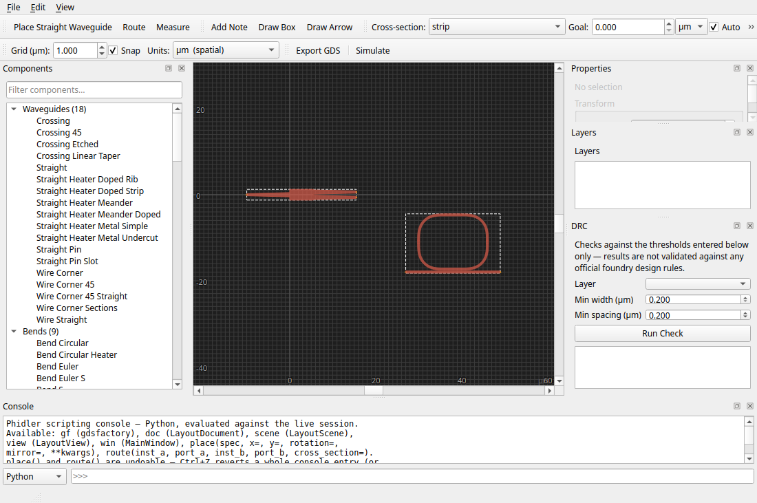
Align snaps a selection to a shared edge or centre:
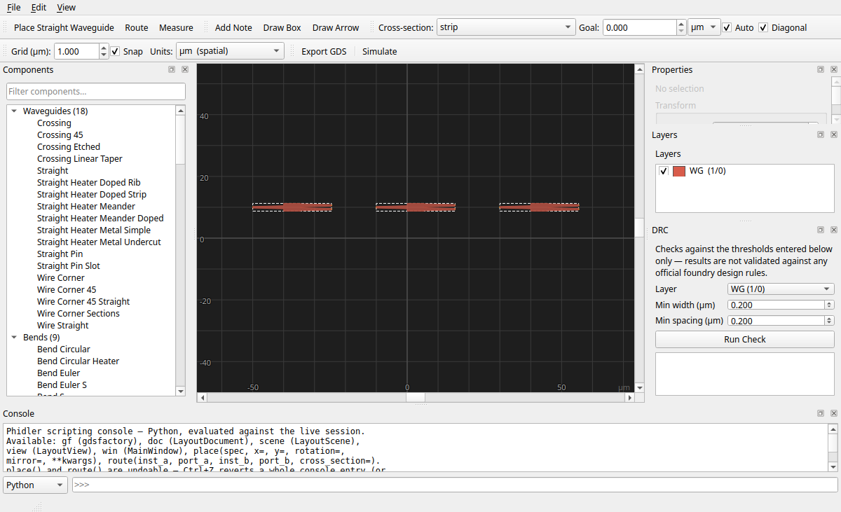
…and Distribute spaces three or more evenly:
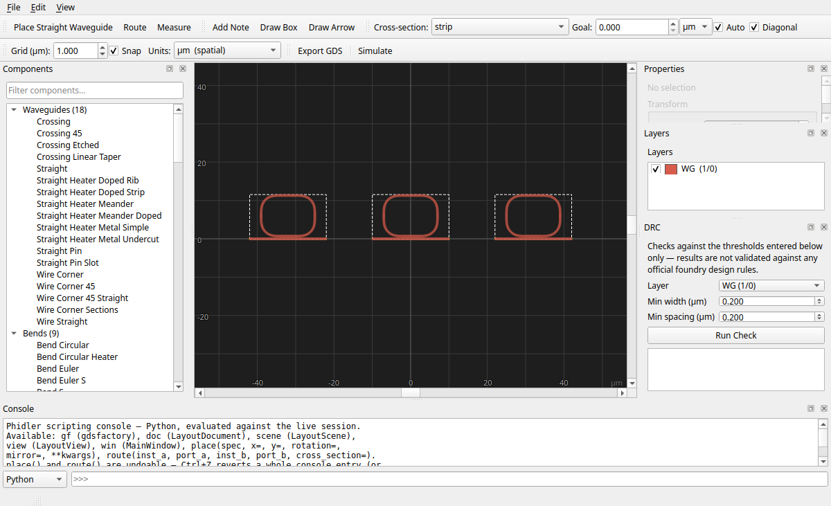
A background grid keeps things tidy. With Snap on, placement, dragging, and routing all round to the grid pitch you set.

Array a component
Need a fiber array, a bank of rings, or a splitter tree? Set columns, rows, and pitch in the Array section and Phidler tiles the component as a single unit.
Route between ports
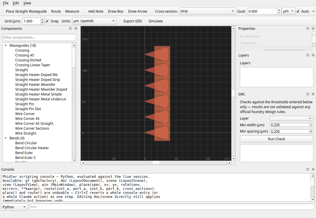
Click a port, then another, and Phidler draws a waveguide between them. Pick the cross-section the route is drawn with, and route with all-angle diagonal bends or Manhattan. Here's the good part: set a goal length and let Phidler insert an adiabatic meander to hit it, so matched delays come for free.
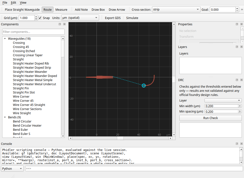

Select a route to read back its exact length and propagation time, including how far it lands from your goal.
Measure
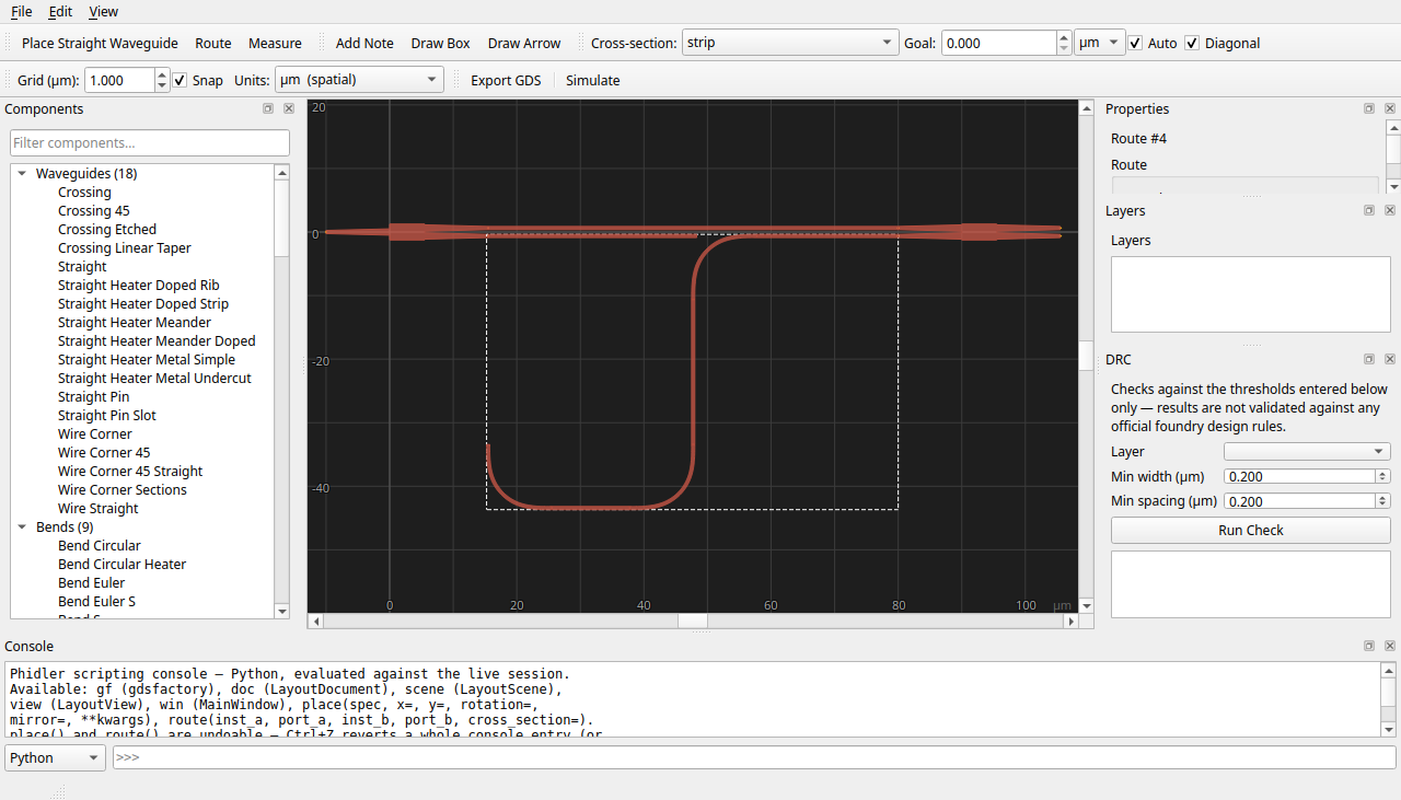
The measure tool reports the distance between any two points, snapping to nearby ports, with a dimension annotation right on the canvas.
Distance or delay
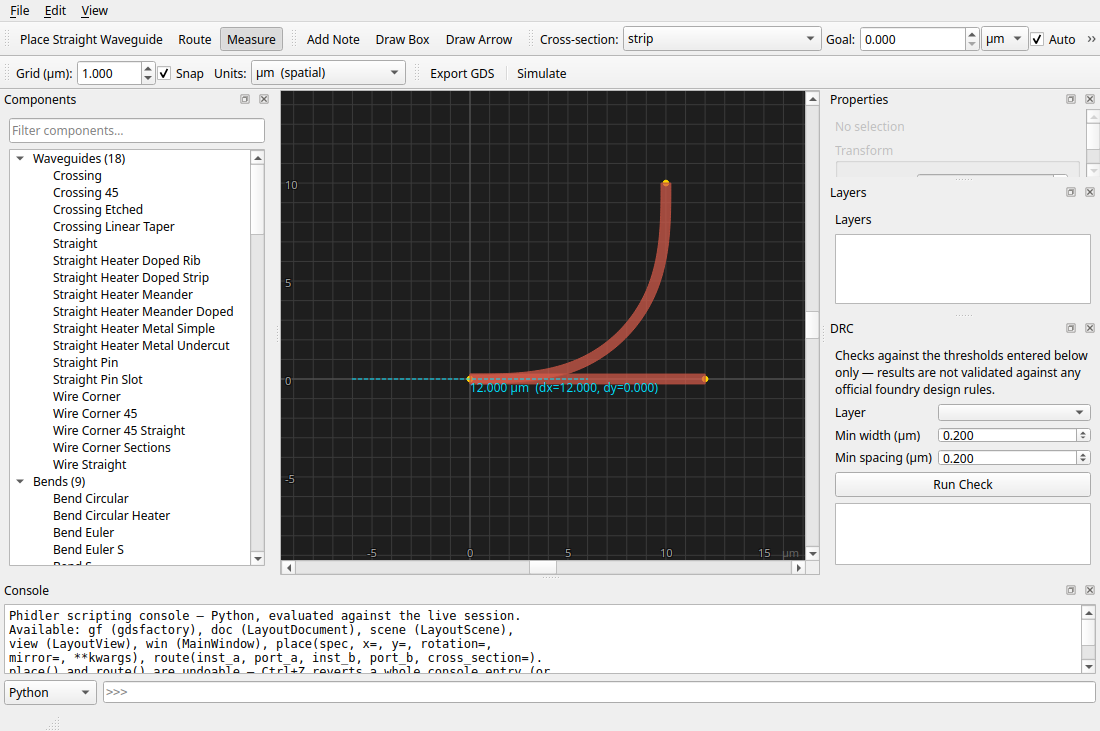
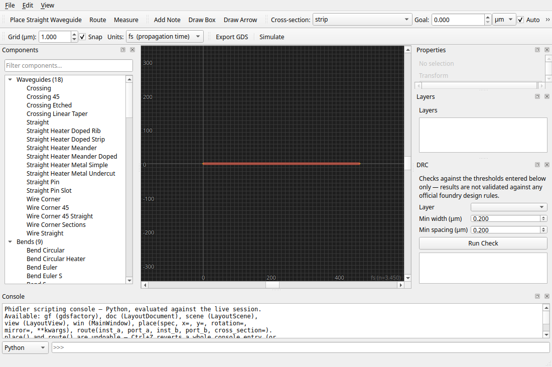
Switch the Units control from microns to propagation time and the rulers and readouts re-express length as time-of-flight (fs / ns), using the effective index from your last mode solve. It's the view that matters when you're budgeting delays.
Layers
The Layers panel lists every layer actually used by your design, with a visibility toggle and an editable colour per layer.

Trace over a reference
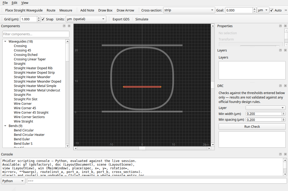
Import an existing GDS as a dimmed, non-editable backdrop and lay your design over it. Handy for matching an existing chip or a supplied floorplan.
Check design rules
A quick DRC checks minimum width and spacing on a chosen layer and lists the violations; click one to zoom straight to it on the canvas.


Simulate with FDTD
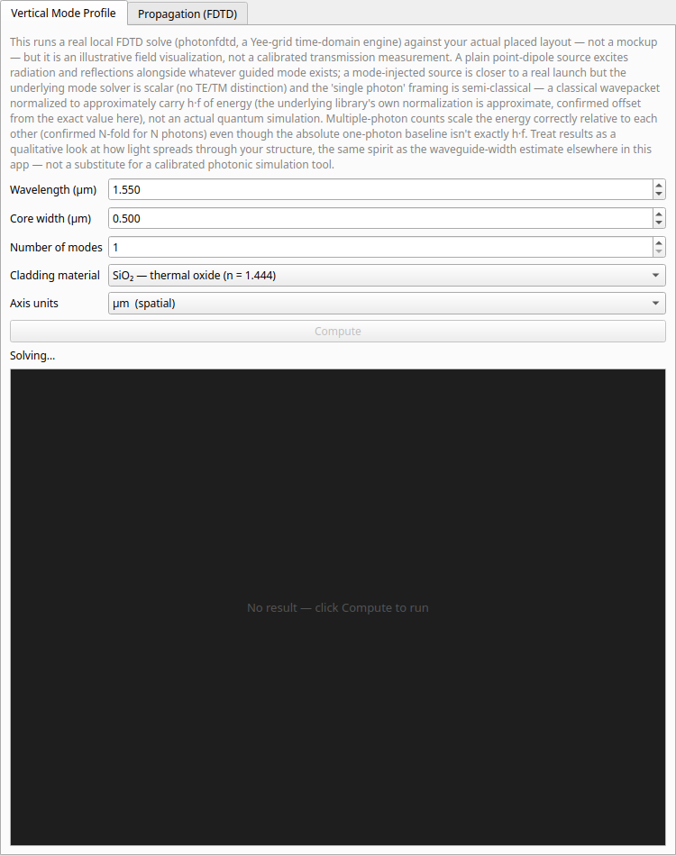
Phidler ships a real FDTD engine (finite-difference time-domain, the workhorse method for simulating how light moves through a structure). Start with the vertical mode profile: solve the guided mode of your waveguide cross-section and see its field and effective index.
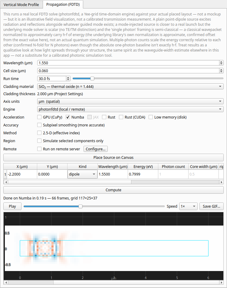
Then place sources on the canvas (a plain dipole, a mode-matched single photon, a scripted waveform, or a Cherenkov track), pick the cladding material, choose CPU/Numba/GPU, and run.


Watch the pulse propagate through your actual layout, scrub the field movie frame by frame, and export it as an animated GIF.
Runs too big for your laptop? Offload to a GPU (NVIDIA CUDA or AMD ROCm) or to a remote server over SSH. The progress bar and results come back the same either way.

Script it when you want to
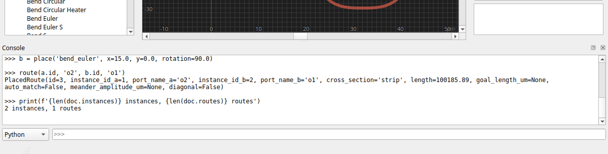
For anything the UI doesn't cover, a scripting console runs Python against
the live session with gf, the document, and place()/route() helpers. Mix
clicking and code freely.
Or just ask Claude
Don't feel like clicking or writing code? Switch the Console to Ask Claude
and describe what you want — "add a 2×2 MMI and route both outputs to the grating
couplers." Claude builds it on the live canvas through the same session the
console uses, so you watch every edit land (and it reads whatever you've got
selected, so "route these two" works). It's optional: you need the ai extra and
the Claude Code CLI installed.
What you can build
From a single waveguide to a full circuit: splitters and combiners, ring resonators and add–drop filters, fiber-coupler arrays, delay lines, and interferometers. Lay it out visually and export it as GDS.
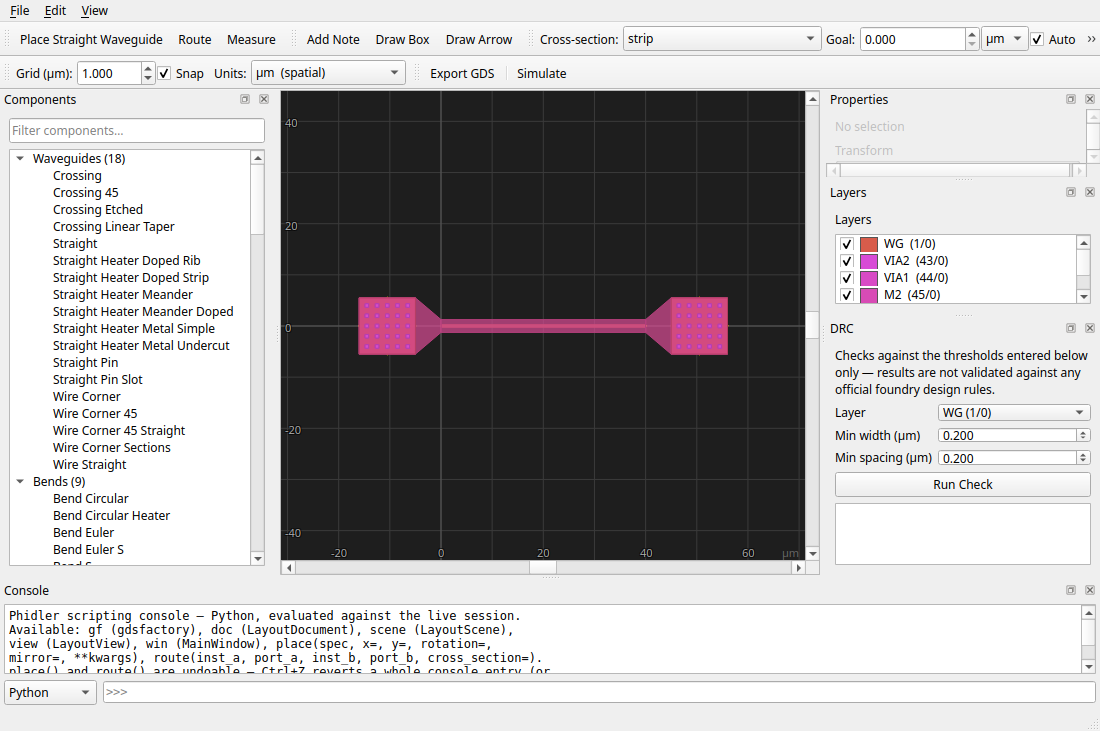
Active devices too. Here's a thermo-optic phase shifter, its metal heater and via stack sitting over the optical waveguide (note the metal layers in the Layers panel).
Save & export
Projects save to an editable .phidler file that remembers your whole
design and simulation set-up. When you're done, export a foundry-ready
GDSII, or a Python script that rebuilds the layout in gdsfactory.

Ready to build one yourself? Start the MZI Tutorial »